
Description
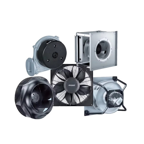
Products Description
Technical Description
| Weight | 38.5 kg |
|---|---|
| Motor size | 150 |
| Size | 560 mm |
| Rotor surface | Painted black |
| Electronics housing material | Die-cast aluminum |
| Impeller material | Sheet aluminum |
| Number of blades | 5 |
| Direction of rotation | Clockwise, viewed toward rotor |
| Degree of protection | IP55 |
| Insulation class | "F" |
| Moisture (F) / Environmental (H) protection class | H1 |
| Max. permitted ambient temp. for motor (transport/storage) | +80 °C |
| Min. permitted ambient temp. for motor (transport/storage) | -40 °C |
| Installation position | Shaft horizontal or rotor on bottom; rotor on top on request |
| Condensation drainage holes | On rotor side |
| Mode | S1 |
| Motor bearing | Ball bearing |
| Technical features | - Output 10 VDC, max. 10 mA - Output 20 VDC, max. 50 mA - Output for slave 0-10 V - Operation and alarm display - Input for sensor 0-10 V or 4-20 mA - External 24 V input (parameter setting) - External release input - Alarm relay - Integrated PID controller - Power limiter - Motor current limitation - PFC, passive - RS-485 MODBUS-RTU - Soft start - Control input 0-10 VDC / PWM - Control interface with SELV potential safely disconnected from the mains - Thermal overload protection for electronics/motor - Line undervoltage / phase failure detection |
| EMC immunity to interference | According to EN 61000-6-2 (industrial environment) |
| EMC interference emission | According to EN 61000-6-3 (household environment), except EN 61000-3-2 for professionally used equipment with a total rated power greater than 1 kW |
| Touch current according to IEC 60990 (measuring circuit Fig. 4, TN system) | <= 3,5 mA |
| Electrical hookup | Terminal box |
| Motor protection | Reverse polarity and locked-rotor protection |
| Protection class assignment | I; If a protective earth is connected by the customer|This component for installation may have several local protection classes. This information relates to this component’s basic design.|The final protection class is based on the component’s intended installation and connection. |
| Conformity with standards | EN 61800-5-1 / CE |
| Approval | UL 1004-7 + 60730-1 / EAC / CSA C22.2 No. 77 + CAN/CSA-E60730-1 |
Data according to ErP directive
| Installation category | A |
|---|---|
| Efficiency category | static |
| Closed-loop speed control | ja |
| Specific ratio* | 1,01 |
| *Specific ratio = 1 + psf / 100 000 | |
| Actual | Request 2015 | ||
|---|---|---|---|
| Overall efficiency ηe | 70,2 | 58,9 | |
| Efficiency grade N | 73,3 | 62 | |
| Power input Pe | KW | 5,03 | |
| Airflow qV | m3/h | 11760 | |
| Pressure increase total | Pa | 1035 | |
| Speed n | min-1 | 1770 | |
| Data established at point of optimum efficiency | |||
Nominal data
| Phase | 3~ | |
|---|---|---|
| Type of voltage | AC | |
| Nominal voltage | in V | 400 |
| Nominal voltage range | in V | 380 .. 480 |
| Frequency | in Hz | 50/60 |
| Type of data definition | maximum load | |
| Speed | in min-1 | 1760 |
| Power input | in W | 5000 |
| Current draw | in A | 7,7 |
| Max. ambient temperature | in °C | 50 |
Curves
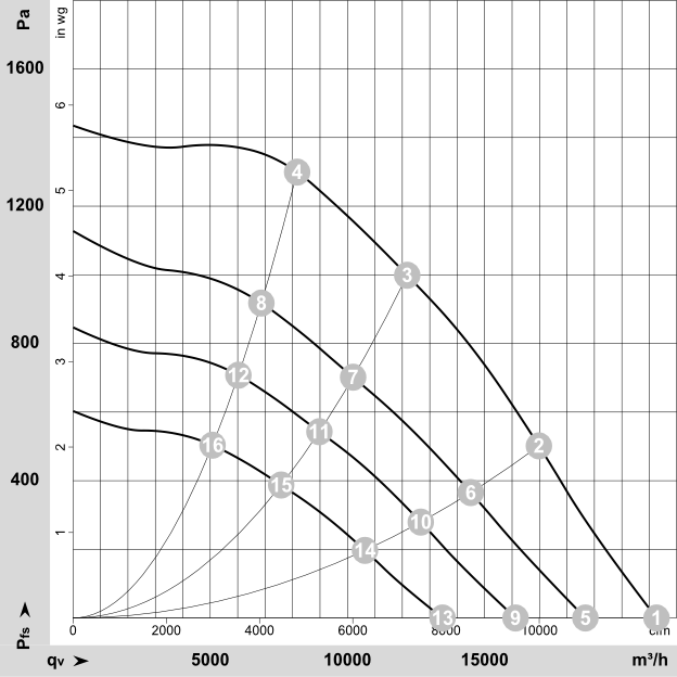
Air flow 50 Hz
Air flow 50 Hz
Measured values
| n | Pe | I | LpAin | |
|---|---|---|---|---|
| in min-1 | in W | in A | in dB(A) | |
| 1 | 1760 | 2788 | 4,36 | 95 |
| 10 | 1324 | 1802 | 2,96 | 78 |
| 11 | 1304 | 2023 | 3,27 | 70 |
| 12 | 1310 | 1937 | 3,15 | 72 |
| 13 | 1146 | 827 | 1,58 | 81 |
| 14 | 1115 | 1113 | 2,04 | 73 |
| 15 | 1101 | 1271 | 2,25 | 65 |
| 16 | 1105 | 1212 | 2,17 | 67 |
| 2 | 1760 | 4251 | 6,52 | 85 |
| 3 | 1760 | 5000 | 7,7 | 77 |
| 4 | 1760 | 4788 | 7,32 | 80 |
| 5 | 1574 | 1956 | 3,17 | 90 |
| 6 | 1511 | 2650 | 4,16 | 80 |
| 7 | 1482 | 2956 | 4,61 | 73 |
| 8 | 1492 | 2845 | 4,45 | 75 |
| 9 | 1364 | 1306 | 2,29 | 85 |
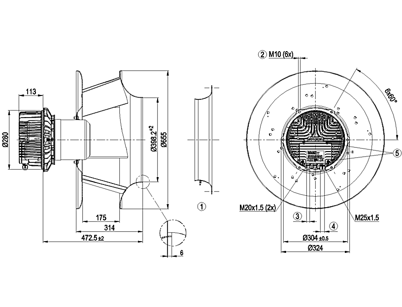
Drawing
- online service
- +86 188 1437 3532
- support@baizhouboms.com
-
We chat